John Shovic's Google Plus Switch

Wednesday, March 26, 2014

Project Curacao Operational

Project Curacao has now been down in the Caribbean for two weeks now.  We've had some issues but they have been resolved.  We are writing an article for MagPi magazine describing all of our issues with the box and the wind turbine.  Major points are:

1) Minor problems with the box and shipment.  Loose grounds, unplugged sensors (looks like the TSA picked up the box by the outside temperature sensor).  No problem at all with the TSA.  We put in a letter in the box describing the project and copies of articles we had written and it went through with no problems.
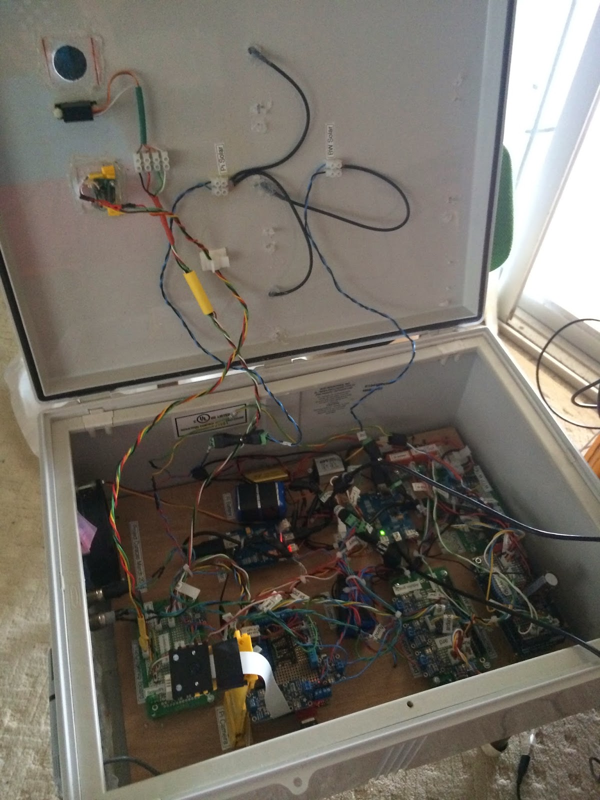
Pre-installation Checkout

2) The special hardware to mount the box to the tower did not fit.  We had to strap it to the tower and orient the solar panels perpendicular to the ground.  
Mounting Platform
Installation
Installed Project Curacao


3) Lower solar power than design.  The strapping on the side of the tower would work in Idaho (45 degrees latitude) but gives very little power in Curacao (12 degrees latitude).  The problem with this was not with the Raspberry Pi.  It was with the Battery Watchdog Arduino.  We adjusted the run time of the Pi with the Arduino to fit the available power.  However, the Arduino is meant to run 100% of the time and the behavior of the Arduino is ill-defined in very low battery conditions.  It would glitch the real time clock which gave some very random behavior. 

We fixed this by moving the box down off the tower and onto the roof until we get a new mounting platform.

Arduino Control Screen
Note on the RasPiConnect  (www.milocreek.com) screen above you can see the Arduino battery voltage going down and down and down until we turned it off for a few days and moved it to the roof.

Here is a picture from the box's new location (again from RasPiConnect):


Camera Subsystem Control Screen

Here is a picture of the box in it's new happy place.


Relaxing in the Caribbean - but with Power


4) The wind turbine worked as predicted by our models.   We switched on the turbine at night to provide a trickle charge to the main computer. We got about 60 - 90ma of current at 15MPH.  No where close to the 200-300ma it takes to run the Pi.  However, a wind storm came through and destroyed the turbine about a week after installation.  Note that the turbine popped out of the stand and throughly destroyed itself.  We think that is was a sympathetic vibration with a particular wind speed (much like the "Galloping Gertie" Tacoma Narrows bridge) since we observed that the stand was flexing in the wind.  We will either prevent the next turbine from popping out or stiffen the stand to prevent the flexing or possibly both.
Destroyed Wind Turbine

We plan to replace the turbine and get a new mounting platform for our September 2014 maintenance trip to Curacao.

Wednesday, March 19, 2014

Software Description Done

We have published the description and architecture of the software system used for Project Curacao. Check out our Project Curacao Software Description page above.

Thursday, March 13, 2014

Project Curacao Installed

Today was the big day.  We mounted the Project Curacao wind turbine and the box up on the tower.  March 13, 2014.

It's running fine.  You can see the graphs and latest picture on http://www.milocreek.com/projectcuracaographs.  Thank you MiloCreek for hosting this page.

The tilt of the box is different than design due to mismatched tower parts.  It's flat rather than tilted up.  Hence the camera shows a lot of roof!  (We are calling it roofcam around here).

It is up and connected to the wireless router even through the metal roof.  The different tilt angle also reduces the solar power to the main unit, so it only runs about 7 hours a day.  The wind turbine may make up the difference.  We will see in a few days.


RasPiConnect Camera Screen


Final Charge before the Installation


The Wind Turbine being Hoisted up the Tower

Installation of the Wind Turbine
Bringing the Box up the Tower
Attaching the Box and the Wind Turbine Wiring
Working in the Sun
The Complete System Installed


Sunday, March 9, 2014

Project on Site

All of our equipment has arrived here on the island.  TSA inspected the box twice, but aside from picking up the box with the outside temperature sensor, pulling the wires off, it survived.  The temperature sensor was fixable.  There were also a couple of loose grounds to be tightened.  A group of sensors were giving odd readings so I knew to look for a loose ground.  One bad sensor, might be the sensor, a bad group likely a ground. 

Remember, you can always trust your mother, but you can never trust your ground.

We have put the box outside for the first time yesterday and the solar cells are working. The wind turbine needs to up on the tower to really roar.  It currently is only generating about 40ma but on the tower it will 200ma or so according to my curves. 

RasPiconnect connected to the box and the first Caribbean picture:


Here is box and turbine enjoying the sun:


Here is John writing this blog entry.  Note that someone stole 200 meters of phone line about a mile from the house and so we have lost our internet correction for some time.  


Wednesday, February 19, 2014

Software Status (02/19/14)

Our release software is done.  It's been in final test for the past week now.  Here is the list of  issues and latest additions.

As of today (02/19/14), the current state of the software in Project Curacao is as follows:

- Arduino Battery Watchdog:  
  1. Control of the wind turbine (selection between solar and turbine).   The Battery Watchdog turns the solar off and the wind turbine on at sunset and turns the solar on at sunrise.  This is time based and not luminosity based.  We will add more smarts to the Pi to look at cloudy days (via luminosity and color sensors) after the system is deployed to Curacao (to be deployed in early March, 2014).
RasPiConnect Screen modified for Wind/Solar Selection


- Project Curacao Pi main program:  The main program is generating all the graphs, camera pictures, environment sensing as required.  It is also regulating the Fan automatically now.    Reading log files from the Arduino Watchdog.  Next  things to be implemented:
  1. Improving sensor error detection (Vastly improved, but still needs more).  We still have an issue with the DHT22 sensor (Humidity Spike as shown below from RasPiConnect).  We believe that we will have to buckle down and figure out the checksum to detect these.  This is a Pi software problem, so we can do it after deployment.


- RasPiConnect:  Complete.  We use this all the time now to monitor what is going on in the project remotely.   
Here's the newest main screen (1 of 6 at this point):

Sunday, February 16, 2014

50W Wind Turbine Loaded Results

Update (03/26/14):  The Wind Turbine was deployed down in Curacao two weeks ago.  The actual data from the Turbine matched this article quite well.  About 60-90ma at 15 MPH.  Not much (and not nearly enough to run the box - takes about 300ma) but it did provide a trickle charge at night.  A windstorm took out the turbine about a week later.  See the blog posting about Project Curacao Operational.


We have now completed the 50W Wind Turbine characterization.  During the test of three weeks ago, we blew out the DC/DC voltage regulator with an over voltage condition. The damage was limited to the regulator.

Why did this happen?

The open loop voltage measurement on the 50W Turbine gives us a clue. The regulator is specified as a maximum 19V input. When the turbine hits more than about 25MPH, we started to generate more than 22V, even loaded. This eventually fried the regulator.

What did we miss in our test setup?

The 50W Wind Turbine very minimal specifications say in perfect conditions we can get 2A at 25V which is 50W. However, if we aren't taking 2A (which is 2X to 4X our maximum), the voltage goes up. Eventually, it killed our regulator. We did not think that one through.

How to fix it?


We added an over voltage circuit on the Wind Turbine side of the DC/DC regulator. The wind turbine is rated at 50W, but we aren't going to trust the number. We built one using TVS diodes and made sure we sized it for about 4A@25V (100W) to cover hurricanes (although in a hurricane, that will be the least of our problems - We would expect the Turbine to be halfway to Aruba by then). We did this by getting a 50W 5 Ohm resistor and putting 10-5W TVS diodes in parallel. TVS diodes operate by shunting excess current when the induced voltage exceeds the avalanche breakdown potential. It is a clamping device, suppressing all over voltages above its breakdown voltage. Like all diodes of this type, it automatically resets when the over voltage goes away.

We set the over voltage protection at 20V to avoid this problem in the future.

A good link for a diode based over voltage protection circuit is http://www.electronics-tutorials.ws/diode/diode_7.html


Completed Overvoltage Circuit


We ran another set of loaded tests for the 50W Turbine after the over voltage circuit was added and got the following curve (without generating any smoke).


Conclusion

We are going to go with the 50W wind turbine for this project down in the Caribbean. Our curve shows some power generation at 15 MPH and it gets really good at about 25 MPH. When we get the box down to Curacao, we are going to further characterize both the 50W and 15W wind turbines.

Our control system takes the weather into account on cloudy days (low luminosity and solar voltage) and turn the wind turbine on. Of course, we will turn the wind turbine on at night all the time. As our curves show, generating even 10W on an ongoing basis from the wind poses a set of special problems. Our next wind powered system will use better (and more expensive) turbines but as this is a secondary source of energy, the chosen 50W turbine will work for Project Curacao.

Friday, February 14, 2014

BM017 / TCS34725 Color Sensor I2C Python driver

We have made one more addition to the hardware on Project Curacao.  We have added a BM017 / TCS34725 RGBC color sensor to the device.  Here is the device attached to the back of the top of the box and then a picture of it peeking through (with the LED turned on for emphasis - it normally operates with the LED off).


This device was purchased from solutions-cubed.com (excellent service and documentation).  Another version (compatible) can be had from Adafruit.

We wrote a Python driver for the BM017 / TCS34725 as we could not find one on the net that met our needs.

It has been posted on github under https://github.com/projectcuracao/PC_BM017CS for anyone who needs such a driver.

We connected the INT line to the LEDON pin (and the VDD_LED to VDD) and now we can switch the interrupt on and off and turn the white LED on and off without burning another GPIO pin.


The example code to test the library and the TCS34725 is below:


#!/usr/bin/python
# example driver for BM017 and TCS34725
import time
import smbus
from Adafruit_I2C import Adafruit_I2C
from PC_BM017CS import BM017
bm017 = BM017(True)
bm017.debug = True
bm017.readStatus()
bm017.isBM017There()
bm017.getColors()
bm017.readStatus()
bm017.disableDevice()
bm017.setIntegrationTimeAndGain(0x00, 0x03)
bm017.getColors()
bm017.readStatus()
bm017.readStatus()
# this will turn on the LED if LEDON is connected to INT and LEDVDD is connected to VDD_LED
bm017.setInterrupt(True)
time.sleep(5.0)
bm017.setInterrupt(False)
And the results:
pi@projectCur ~/PC_BM107CS $ sudo python example.py
BM017 initialized
('BM017 Status=', 17)
BM017 / TCS34725 is present
('ColorList = ', [2, 0, 1, 0, 1, 0, 0, 0])
('clear_color= ', 2)
('red_color= ', 1)
('green_color= ', 1)
('blue_color= ', 0)
('BM017 Status=', 17)
('IT set to:', 0)
('Gain set to:', 3)
('ColorList = ', [8, 15, 157, 7, 105, 5, 151, 3])
('clear_color= ', 3848)
('red_color= ', 1949)
('green_color= ', 1385)
('blue_color= ', 919)
('BM017 Status=', 17)
Interrupt On
Interrupt Off
We pointed the sensor at a spool of red wire.  That's why the "red_color" is higher than the green and blue.